In the past when I finish building a speaker system, I measure the electrical impedance and the SPL frequency response before it even leaves the workshop. I import these measured results into MathCad and proceed to design any correction filters required to compensate for baffle step losses. This filter design effort is usually completed quickly before I actually hear the new system. After assembling the filters and measuring the speakers again, everything is moved from my basement workshop into my listening room. I can finally hear the results of the many months of hard work, with and without the filters, and do any last tweaks to get the best performance possible.
I decided to do things a little differently this time. After the enclosures were done, I wired the drivers directly to the binding post terminals and moved the partially completed system upstairs to hear how it actually sounded. Running the speakers directly off my solid state amp resulted in a very unbalanced sound that was extremely strong at the high end but lacked any semblance of bass performance. Turning up the bass tone control gave a hint of what might be possible. At this point, the speakers were returned to my basement workshop to make a complete set of impedance and SPL frequency response measurements.
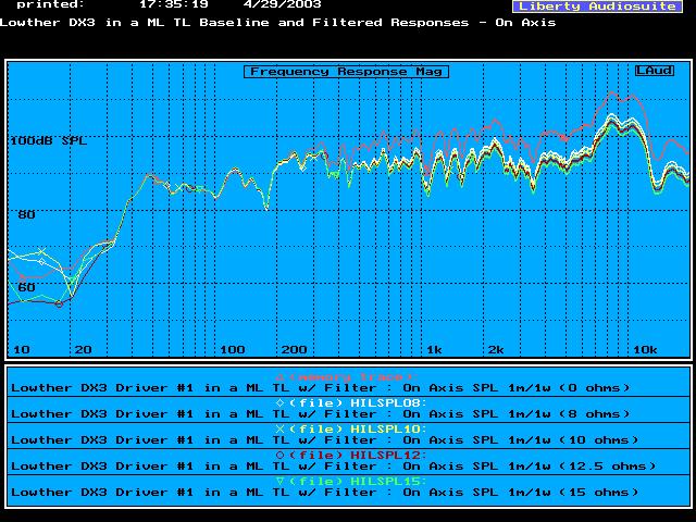
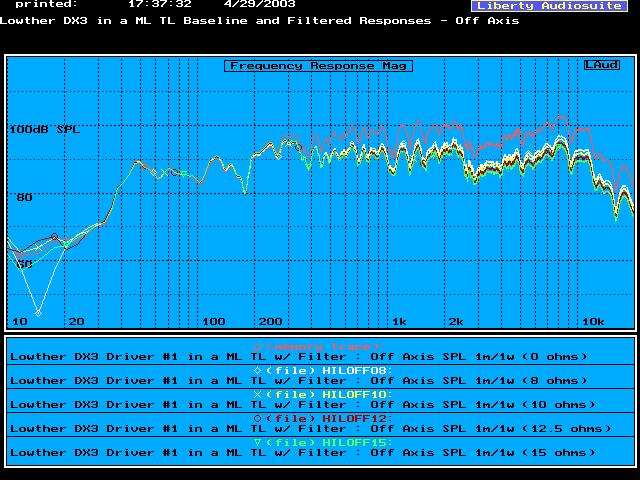
I designated one enclosure Speaker #1 and the other Speaker #2. Since I had previously labeled each pair of Lowther DX drivers #1 and #2, I could keep track of each driver matched with the appropriate enclosure. I have been consistent with this numbering scheme. I measured the impedance and the SPL response at 1 m for 1 watt input, on-axis and off-axis, for each of the DX drivers in their respective enclosure. The measurement technique, set-up, and post-processing described earlier was again applied to the finished speakers. The results were consistent between Systems #1 and #2 and confirmed the initial listening impressions. The results of these measurements are shown below for Speaker #1.
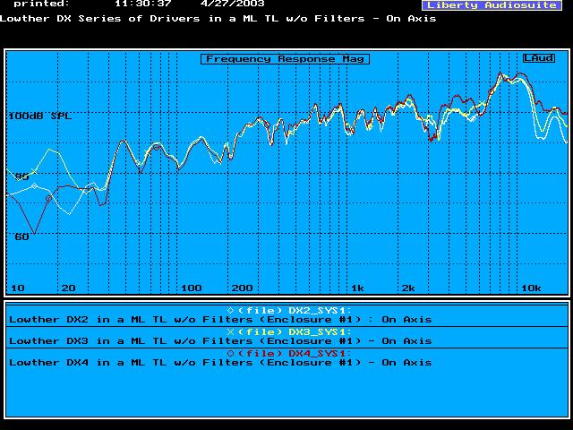
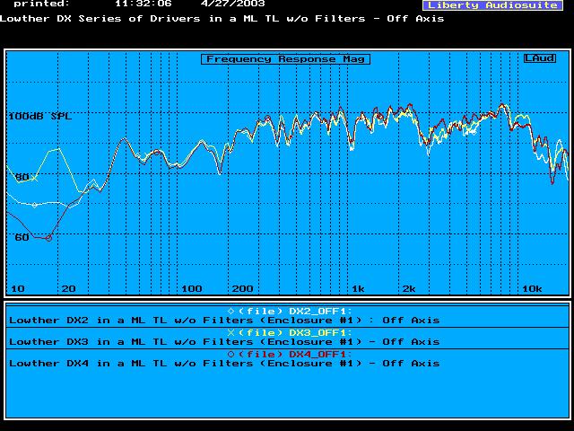
The SPL output is a consistently rising response with increasing frequency. If you consider the SPL response below 100 Hz and the SPL response above 400 Hz there is a 10 to 15 dB increase in SPL output. Based on my initial listening impressions, and the measurements shown above, I did not see any way that this style of enclosure design could be equated to a high performance speaker system without some form of a correction filter or equalizer.
Based on the results of the measurements shown above, I started designing passive filter networks to rebalance the SPL frequency response for the DX2 driver. Again, my goal was to have a common enclosure design and a common filter design, actually a filter with minimal required adjustment, so that any of the DX drivers could be used in the final system. To perform the calculations required to design this filter network, I read the impedance and SPL, on and off axis, into MathCad for each of the drivers in their finished speaker enclosure.
The first piece of the filter network to be sized was a Zobel circuit to go across the speaker input terminals. A Zobel circuit is used to offset any voice coil inductance and produce purely resistive impedance above approximately 100 Hz. The voltage applied by the amp is unchanged by this circuit. Only the impedance seen by the amp is changed.
Then I added a resistor in parallel with an iron core inductor in the positive lead to the driver. This second circuit is intended to shelve down the rising high frequency response by a predetermined number of dB's. This second filter shapes the voltage being applied to the speaker terminals as a function of frequency. The high frequency SPL response is attenuated. This circuit should not impact the driver's T/S properties or dynamic performance significantly.
When I designed the resistor to be placed in parallel with the inductor, I decided to use a little lower resistance value and to not try and fully correct the 6 dB baffle step loss typically seen at low frequencies in an anechoic environment. In my previous projects, I did design for a full 6 dB of correction and ended up with the bass performance being a little bit too strong and significantly lower efficiency. For the Lowther DX drivers I decided to design for 3 to 4 dB of correction and use some room reinforcement to supplement the bass response from the speaker. I estimated the increase in bass SPL performance using a room response MathCad worksheet I had written a few years ago.
The process described above was repeated for each of the Lowther DX3 and DX4 drivers. The impedance and SPL response measurements, on axis and off axis, were read into MathCad for the DX3 and DX4 drivers mounted in the ML TL enclosures. The same Zobel correction circuit was placed across the speaker terminals. The baffle step correction circuit was added in series with the DX3 and DX4 drivers in the positive lead. The corrected (rebalanced) SPL response was calculated for a variety of BSC circuit parallel resistors. The same circuit works for any of the Lowther DX drivers. The only adjustment is the value of the parallel resistor. For this resistor, I purchased four different values of Mills resistors which allowed some tuning of the final system response. Depending on the particular DX driver, the room, and the type of amp being used one of these resistors should cover almost any situation. I suspect that if a low damping factor tube amp was used to drive these speakers, then an even lower resistance value might prove to be optimal.
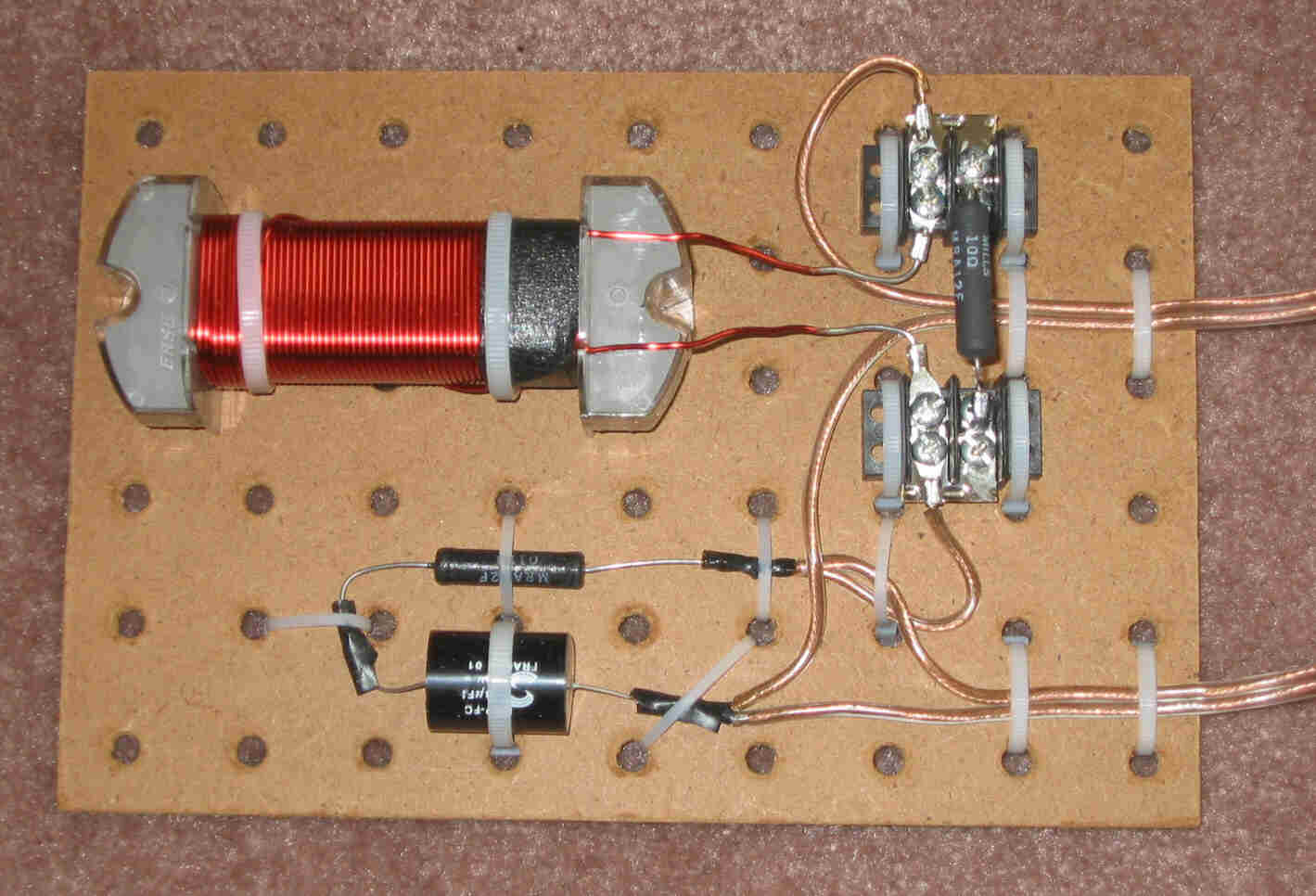
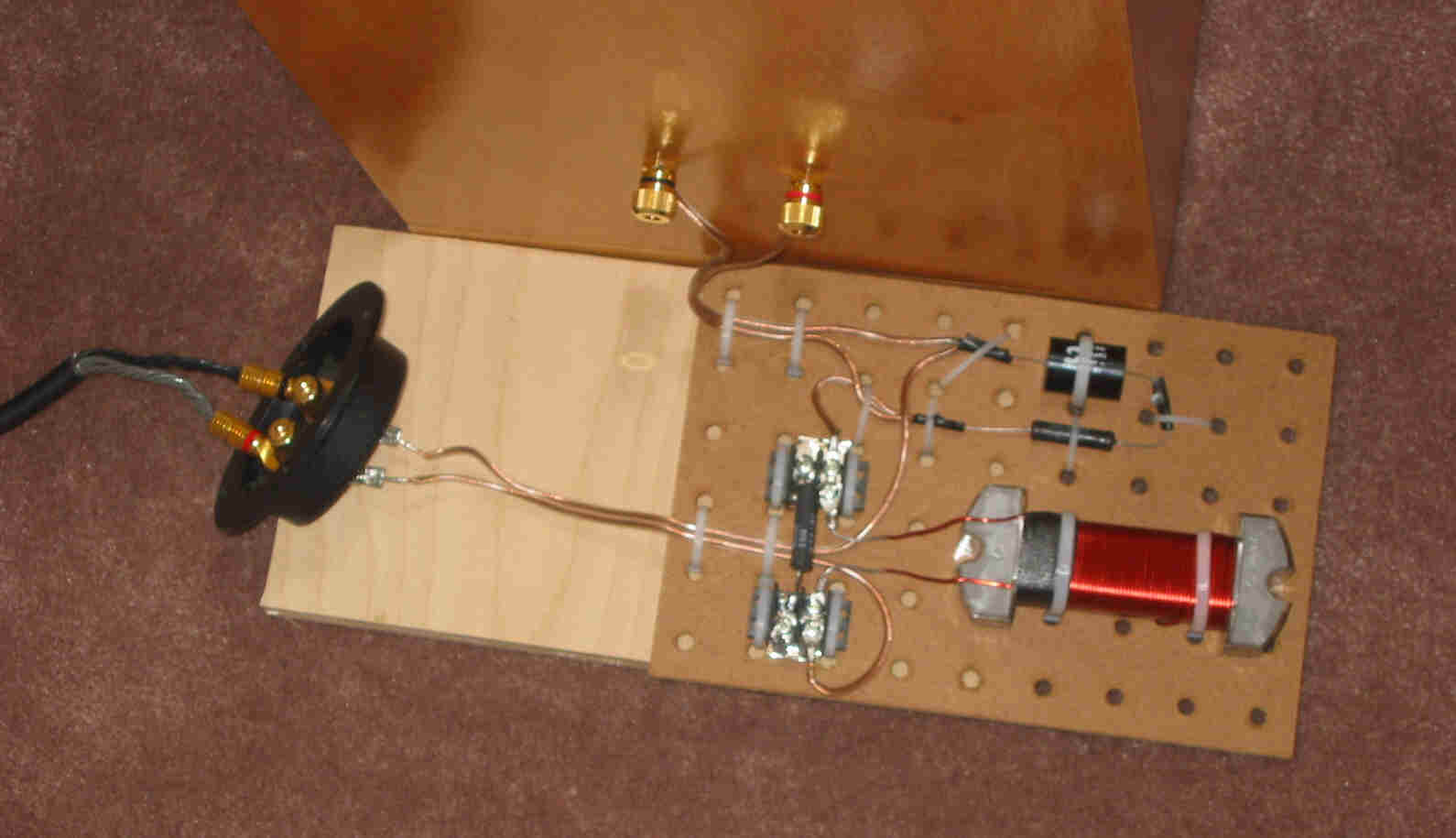
As an example of the filter design process and the predicteded results, the DX3 MathCad worksheet is provided. Similar worksheets were run for all of the individual Lowther DX drivers in their appropriate enclosures. The result of these calculations was a schematic and parts list for the Lowther DX series project. Finally the following two pictures show the temporary assembled circuit and the temporary connection arrangement I have been using to tweak the final parallel resistor value.
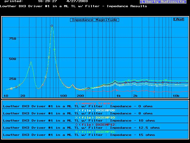
With the correction circuit in place, I measured the finished DX3 system performance with the five different possible values for the parallel resistor. By presenting all of these curves together on one plot, you can see the changes in the impedance and the SPL frequency response as a function of the parallel resistor value. With any of the parallel resistors the SPL response is now much better balanced and efficiency between 90 and 95 dB at 1 m for 1 watt input is maintained above 200 Hz. With some room lift reinforcing the response below 200 Hz, the system will be well balanced while still very efficient.
The Lowther DX3 drivers eventually became the permanent drivers for these enclosures. As they continued to break-in, I started to consider redesigning the baffle step correction circuit (BSC circuit) to reduce the amount of attenuation that I had originally applied and to raise the frequency where the BSC circuit became active. In addition, I decided to try and extend the high frequency response using a capacitor in parallel with the BSC circuit as I had done successfully in Project #3.
For several weeks, I tweaked the values of the circuit components and listened to the changes until I felt that I had an optimum combination of values. The result of this redesign was a schematic and parts list for the new BSC circuit. The modified BSC circuit will also work well with a Lowther DX2 driver but it is not optimum for a Lowther DX4 driver.