I spent several months trying to optimize different styles of quarter wavelength enclosure to see which would work best with the Lowther DX series of drivers. I ran MathCad simulations of bass reflex enclosures, transmission lines, TQWT's, back loaded horns, ML TL's, and double bass reflex enclosures. Eventually, I narrowed down the choices to a ML TL and a ML TQWT enclosure. The calculated response for each was almost identical. Both of these designs would require some value of additional series resistance to rebalance the rising high frequency SPL response.
I decided to build the ML TL enclosure design due to the very simple construction and the relatively compact size. The MathCad ML TL simulations for the DX2, DX3, and DX4 drivers are included in pdf format. One of the features I liked about the ML TL enclosure design is that it would take any of the three DX drivers. It appeared to be an enclosure that somebody could build for a DX2 driver and than have an upgrade path to the more expensive DX3 or DX4 drivers.
I have been asked many times about the difference between a ML TL design and a simple bass reflex enclosure. From the outside the two look very similar and performance wise there is not a large difference. I think that the principle difference is the way the air volume in the cabinet is used to provide the spring that interacts with the mass of air in the port to form a resonant system.
In a bass reflex cabinet, the air in the box is compressed to a uniform pressure to form an air spring. Typically no damping material is added to the inside of the box so that the Q of the box remains high and the effective volume of air is predictable from the internal dimensions of the box. The shape of the bass reflex box is not that critical, only the internal volume matters. A bass reflex enclosure can be represented as a lumped mass hanging on a spring. If you displace the mass the entire spring stretches. When you let go, the mass oscillates at a predictable frequency that is a function of the springrate and the mass of air in the port. The key point is that the entire spring stretches linearly. This is a simple one degree of freedom mechanical system.
In my opinion, one of the negative attributes of a bass reflex enclosure is that any strong standing wave resonances in the enclosure will not be sufficiently damped. The lack of fiber in the center of the air volume allows energy from the back of the driver to potentially excite resonances and produce unwanted acoustic output that escapes through the port opening. Some people try and mitigate this problem by placing the port on the back of the enclosure. Placing the port on the back of the bass reflex enclosure may require more standoff from the rear wall and lead to room placement problems. The ML TL enclosure design requires stuffing in the internal volume of the enclosure. The presence of this stuffing is part of the design cycle and the amount and location is accounted for in the design process.
The ML TL enclosure can be thought of as a form of transmission line where quarter wavelength standing waves are used to provide the spring for the mass of air in the port. To physically model a straight uniform TL, clamp a yardstick to the edge of a counter or desk and pluck the free end so that it starts to vibrate. The vibration pattern is analogous to the air velocity in a TL. The TL's air velocity is zero at the closed end as is the yardstick's motion at the clamped end. The TL's air velocity is a maximum at the open end as is the yardstick's velocity at the free end.
There are two ways of changing the frequency of vibration for the yardstick. If you shorten the length cantilevered off the counter, the frequency of vibration will increase. Make the length longer and the frequency decreases. This is how straight TL's have traditionally been tuned by adjusting the length. The second way of tuning the frequency of the yardstick is to add a lump of mass to the free end. Put a piece of modeling clay on the free end and watch the frequency decrease. What I have done to the classic TL is put a lump of mass at the terminus end using a restrictive port. For a given frequency, I can shorten the TL (make it stiffer) increasing the tuning frequency and then add mass (air in a port) to pull the frequency back down and get a similar tuned result. One other benefit of having a lump of mass at the terminus is a rolled off port output above the first quarter wavelength resonance. This result is similar to a bass reflex port's response. I did this first with the ML TQWT and then with a straight TL. If you try the yardstick analogy, I think by changing the length and adding mass to the end you can demonstrate to yourself exactly what I am doing in my MathCad computer models.
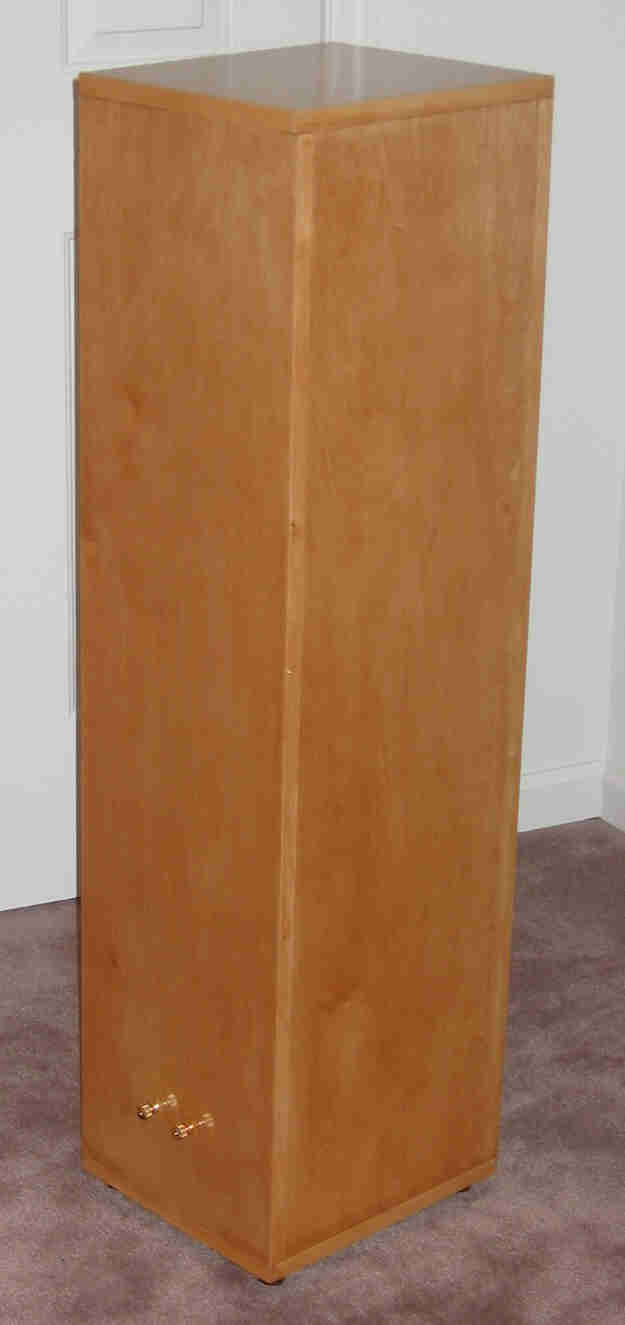
Having decided to build a ML TL that would work with any of the Lowther DX drivers, I sketched up some plans. The final set of plans is available in pdf format. A single sheet of 3/4 inch birch veneer plywood was used to make the fronts, backs, and sides. Some extra pieces of the same type of plywood, left over from an earlier project, were used to make the tops and bottoms of the cabinets. I cut the front, back, and sides to width using a table saw. Then using a sliding wooden table that fits into the miter gauge slots on the table saw, I cross-cut all of these pieces to the correct length. After cutting the holes for the driver and port in the front baffles, I drilled two 1/4 inch holes in the back for the positive and negative binding post terminals. The front, back, and sides for each enclosure were assembled using yellow carpenter's glue and a biscuit joiner.
When the glue had dried, I measured each end of the enclosures and custom cut two top and two bottom pieces. Again, using the biscuit joiner the top of each cabinet was glued on. When the glue had dried, I sealed every joint with a thick bead of yellow carpenter's glue.
Making a removable bottom was reasonably simple. I cut eight smaller blocks approximately two inches square. Four of the blocks were attached to the inside of each enclosure, along the bottom edge, centered on the front, back, and sides to provide material for a screw to penetrate. Rubber feet were attached to the bottom panels, at each corner, one inch in from the edges. Using four long screws the bottom was secured to the cabinet. To assure an air tight seal, I placed foam Weather Strip on the bottom panel in a rectangular shape to match the base of the enclosure. Tightening the four long screws, centered on each edge into the smaller blocks mentioned above, compressed this seal nicely. With a removable bottom, the wiring, stuffing, and port installation could now be completed and adjusted easily.
Before adding the drivers, ports, stuffing, and binding posts I stained the cabinets with a Golden Pecan Minwax stain. I used a Minwax wood preconditioner just prior to staining which helped achieve even coloring without blotching. Final finishing was completed with several coats of satin polyurethane and then a final coat of gloss polyurethane.
To hold the stuffing in the top of the cabinet, I added a small plywood cross member 30 inches from the top inside of the enclosure. This cross member is nonstructural and was only intended to hold the stuffing in the top of the enclosure. Then I measured 220 gm (0.25 lb/ft3) of Dacron Hollofil II stuffing and after teasing, wrapped it in a cheese cloth sleeve. The ends of the sleeve were tied shut with string. The sleeve was inserted into the upper section of the cabinet and then the cross member positioned for support.
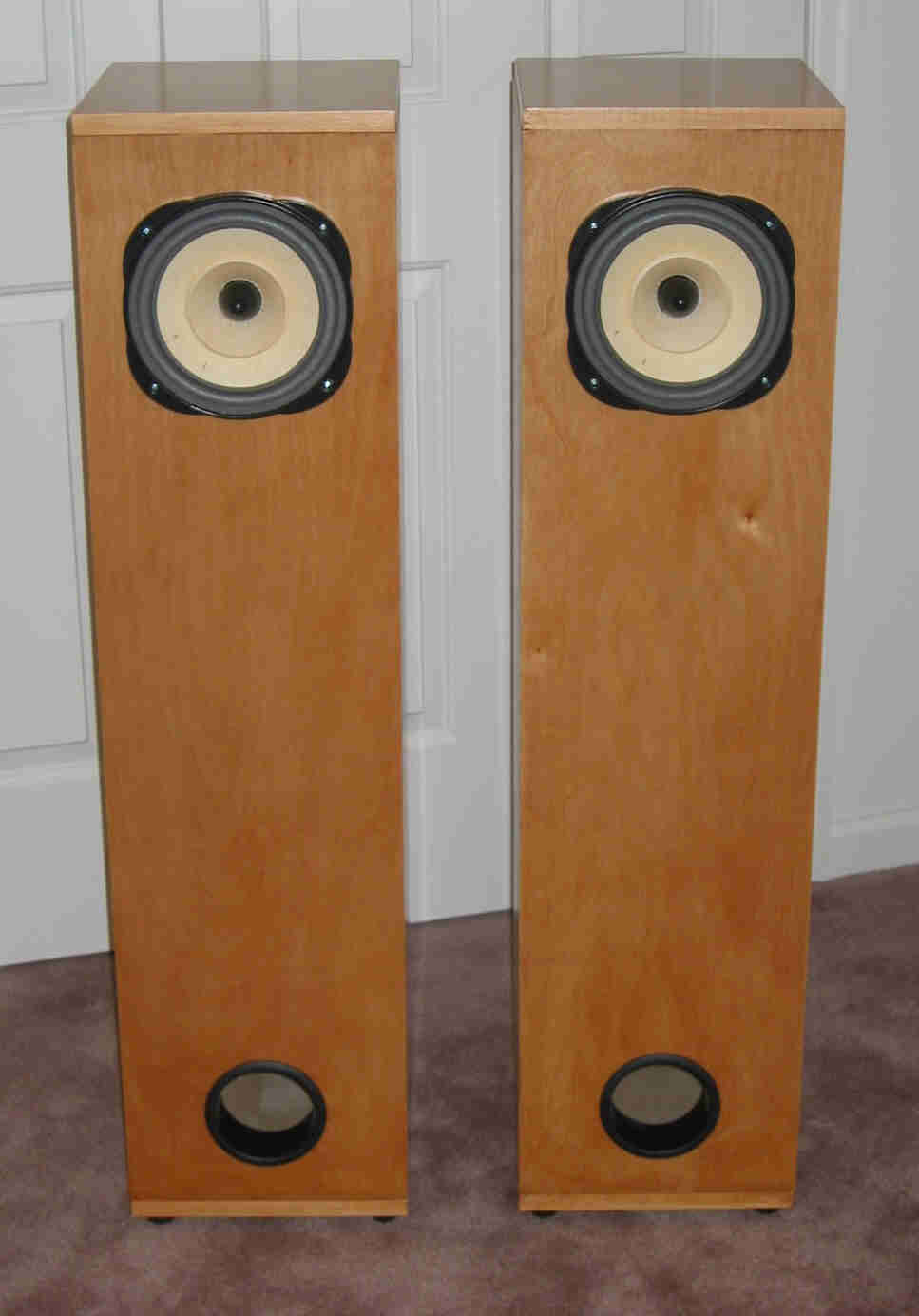
The diameter of the hole for the port, in the front panel, was cut about 1/4 of an inch oversized. A wrap of 3/16 thick Weather Strip was applied to the outside of the port. The port was squeezed into the hole resulting in a snug and secure fit. I bought three pairs of ports that could be trimmed to different lengths and inserted into the enclosure in this manner.
Wiring the driver was easy. A length of speaker wire was soldered to the binding post terminals inserted through the back panel and then threaded up through the open driver hole in the front panel. After double checking the polarity, the wire was attached to the Lowther driver lugs. The driver was inserted and screwed into place using a Weather Strip gasket that I custom cut to width. To hold the drivers in the enclosure, I used four T-nuts and matching machine screws. This method of securing the driver allowed quick and easy disassembly and replacement with a different DX driver. Finally, the bottom of the cabinet was attached and the speakers were ready for action.